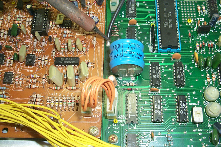
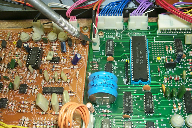
1-1: With the Polysix hood up, locate the heavy (#10AWG or so), black grounding wire running from the KLM-370-- which is mounted to the front panel--to the KLM-367 board's left edge.
1-2: Using a low-wattage (perferably temperature-controlled) soldering
iron, desolder the black wire at the point it is attached to the KLM-367,
as shown.
1-2: Tuck the free end of the wire under any of the cable harnesses to keep it out of the way for now.
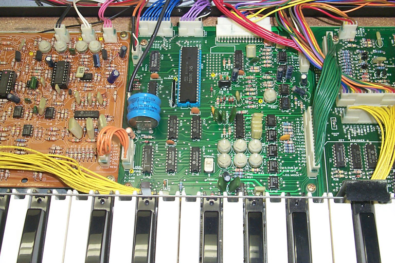
CN08, CN06, CN11, skip over CN10 for now, CN02, CN05 and CN03. Referring to the KLM-367 image for this particular Polysix, here are the cable colors to help clearly note the connectors in addition to the board labels: CN08--one red, one brown and a small orange coax; CN06--all blue wires; CN11--five violet, one white, one black; CN02--all red wires; CN05--all green wires; CN03--all orange wires.
For each connector, after carefully cutting through the glue, start to work the upper connector+cable assembly out of the corresponding socket. These things can be stubborn, so watch the amount of force applied. Do NOT wiggle the connectors from side to side, this weakens the pins soldered to the KLM-367. If one or more connectors are being troublesome, grasp the connector shell at either end and try to "rock" the connector up and out along the connector's length. If you can fit the tip of a small, flat-tip screwdriver between the socket and connector along the open edge, it will help. Most connectors will give a final 'crack' as the glue that managed to get inside breaks, at which point the connector easily pops out. Take your time--there is no rush. Note that CN10 is still connected; we'll get to that in a bit.