4-1: Take the RE! board and orient it as shown below. The "tab" with the mounting hole in it on the RE! board should be toward the right and pointing toward the back of the DX7:
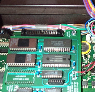
4-2: Take time with this step; done properly it is easy, but done improperly will lead to a troubleshooting session later. Take the RE! board and align it over the ROM socket IC14 such that the pins extending down from the RE! board ROM socket header align exactly with the every socket hole for IC14. Be very sure that the alignment is not "off by one" in either direction or is otherwise misaligned. Also, when properly aligned, the toothpick steadying the spacer should pass through the RE! board mounting hole on the little tab described above. It is difficult to show the alignment by camera, but here is what one end of the socket/header pairing shows (click on image to enlarge):
Note: If you have one, use an angled dental mirror or utility mirror (Radio Shack has them) to "look under" the RE! board from various edges to confirm the proper alignment. In doing so you might notice the 7-pin header extending down to RAM socket IC21. When the primary header for IC14 is properly aligned, this second header will also be properly aligned so as to plug into the last seven pins ofthe RAM socket.
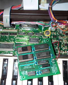
4-3: Once the RE! is aligned with the DX7 DM board, simply place your finger over the area marked "J1" (between the 28 pins of the socket header stick up) and press the header down until it is fully seated onto the ROM socket. Then, place a finger near the "J2" header (just below the red and black/brown wires on the RE! board) and press down until the board levels out and is firmly seated. The mounting hole/tab should now be resting on the spacer and the toothpick can be removed.
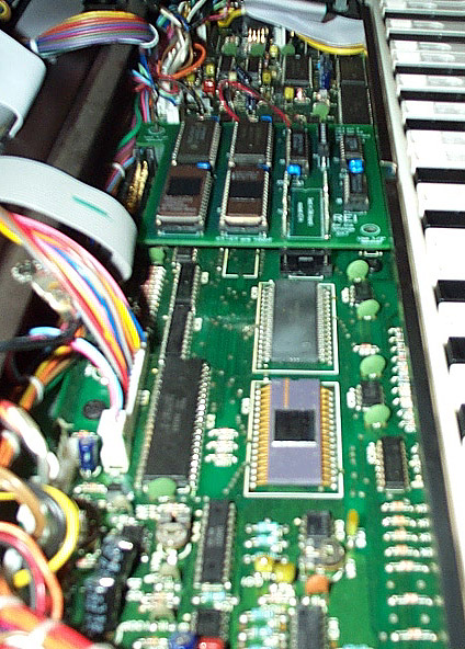
4-4: Take the supplied M4x20mm metric hex-head bolt and place it through the mounting hole and spacer so that it slides down to the DX7 case mounting stud. The bolt should drop in vertically: if it misses the spacer or the bolt/spacer need to be placed at an appreciable angle then the RE! board is probably misaligned in the sockets. If so, then simply use a screwdriver to pop the RE! board out of the IC14 socket and realign it. Once properly aligned and seated, tighten the bolt by hand until it stops, then use pliers or a metric hex driver to tighten 1/4 turn further. Here is the result: