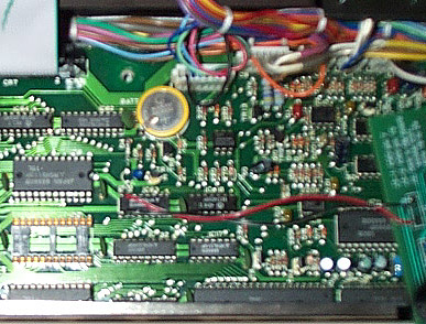
3-1: Locate IC63, which is marked "74LS138" on the top of the chip. Using the images below for reference, IC63 is one chip to the right and one chip up from IC21's empty socket. Notice the red and black wires soldered to the chip in the image. These are the two wires that similarly need soldered for your RE! board to work.
3-2: Solder the exposed end of the RED (or WHITE) wire coming from the RE! board to IC63 pin 7. In the above pictures, pin 7 is the second pin from the left on the top row of pins of IC63. Be careful not to accidentally bridge the IC pins together with solder, and take care to solder to the correct pin.
3-3: Solder the exposed end of the BLACK (or BROWN) wire coming from the RE! board to IC63 pin 10. In the above pictures, pin 10 is the second pin from the left on the bottom row of pins of IC63 (directly below pin 7). As before, take care not to bridge the pins with solder or solder the wire to the wrong pin.
3-4: Take the supplied nylon 0.5" spacer and place it over the hole where the screw was removed near the battery as shown below. Take a toothpick and place it through the spacer and hole. This keeps the spacer from moving when seating the RE! board in the next step.