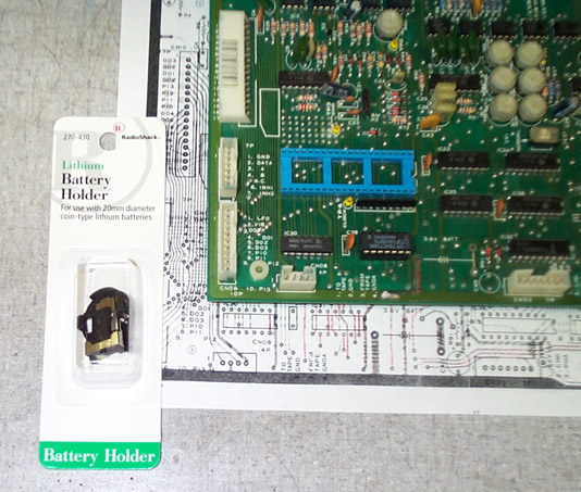
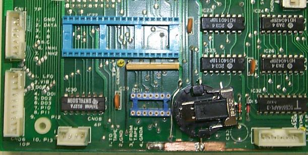
7-2: This particular battery holder has 3 pins that solder to a circuit board. Unfortunately, the pin spacing doesn't quite allow for using all three on the KLM-367. Only two are needed, however, and all that needs to be done is to bend the unused third pin out of the way. These pictures are a little overexposed, but the pin to bend is easily located. Place the battey holder upside-down as shown. On the side of the battery socket nearest to the pliers, note the small pin that is bent such that it sticks out horizontally; this bend is carefully done with the pliers. (The pin is about one inch above the capital letter "B" in the detail drawing):

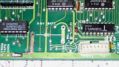
7-3: As mentioned before, resistor R91 and capacitor C40 on the KLM-367 should be removed. Here is the detail image after these parts (just to the right of the battery location) have been removed. Be sure to leave diode D15 alone:
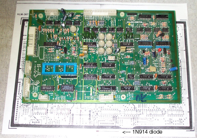
7-4: Here is a (poor) picture of 1N914 diode, Radio Shack part number 900-2904. A 1N4148 (part number 900-2908) can also be used. One could even use a 1N4001 rectifier in a pinch.
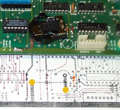
In any case, this diode is soldered into the position the resistor at R91 used to occupy. The diode is polarized: there is a black band near one end of the diode. The banded end of the diode is soldered into the hole of R91 closest to C40. Another way to think of it is the new diode is installed in the opposite direction of D15. In the detail image, the orange diode symbol shows how the "arrow points to the band". Note that the black diode symbol for D15 points in the other direction. Finally, solder the battery holder into place using the two pads marked with yellow dots:
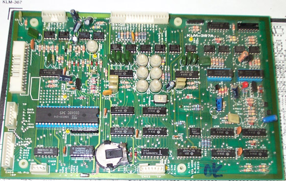
7-5: Check your work, because it is time to reinstall the KLM-367 into your Polysix. As before, note the white plastic holder that the front edge of the circuit board fits into underneath the keyboard. (The KLM-366 is also mounted in the holder; the KLM-367 slides in right next to it.) The KLM-367 is fitted back into place in pretty much the reverse order of removing it: place the board into position and attach the connector that goes to CN06, then slide the KLM-367 toward the keyboard about a centimeter. The front edge of the board should "catch" the holder and fit into place. The KLM-367 is then lowered until level with the KLM-366 and KLM-368 on either side, then replace the four screws.
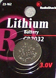
7-6: At this point, all that remains is to install the battery and attach the remaining connectors (and resolder the black grounding wire). The CR2032-type "coin cell" is widely available. The one I got from Radio Shack for this example has part number 23-162:
To install the battery, remove IC31 from it's socket if you installed a socket during this repair procedure. This makes it a bit easier to push the battery into the socket. The battery slides under the clip from the open end with the plus (+) symbol on the battery facing up. The battery will slide in and settle evenly into the holder. Then replace IC31 and the CPU chip IC22: