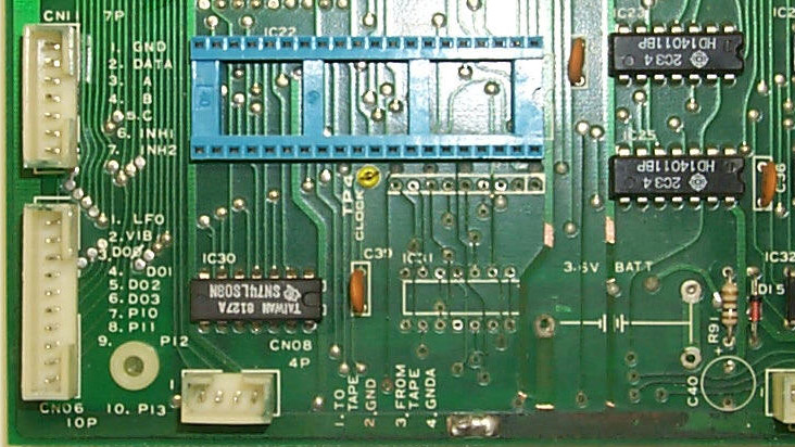

6-2: Now note the wires added to the top of the board as compared with the trace map:

Notice that two of the wires are bare #22AWG solid wire used to replace the heavier traces that were removed. The bare wire with the bend near the top solders to the exposed copper of the intact trace (upper end) and solders into the hole the original trace came from (bottom end). The other bare wire has three connections: soldered to exposed copper at either end, and near the middle it solders to a small wire that goes down into a hole. The small wire is soldered to the pad for this hole on the other side. You might see that there is no bare wire to replace the big trace that was removed. This wire is installed on the bootm, after the battery holder is installed in a later step.
Also notice the two insulated black wires that are soldered to where the original trace "via" holes are located. These wires have about 0.25" of insulation stripped off and are then placed through the holes and soldered on the bottom of the board.
Finally, note that a socket is used for the replacement IC31. (I always put a socket in for repaired/replaced chips). This socket is soldered in place on the bottom of the board. Also note that capacitor "C40" has been removed and that "R91" has been replaced by a diode with the cathode (banded end) pointing down. This is in preparation for the new lithium battery.
6-3: Now to do the wiring on the bottom of the board. This is a lengthy process that involves methodically placing and soldering the repair wires so that the result is neat and functional. Here is how the wiring on the bottom of this board turned out:
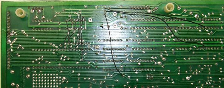
Be prepared to spend a lot of time doing this step. Accuracy is what matters. I usually just do the wiring from left to right following each repair trace in order. Since all the soldering is done on the bottom of the board, you have to use the trace map to see where the upper trace used to go through and connect to the bottom. It took me about 90 minutes to do all the rewiring on this particular board. Take as much time as you need.
NOTE: the 4 longer wires to the right in the above image are not typical of every repair. These replace traces that aren't usually damaged.
6-4: Once the wiring is completed, use a continuity tester or Ohmmeter to check the path of each repaired trace to make sure that a) it is connected and b) it is connected to the right place.