Resonance plots courtesy of Harry Bissell,
Curve and SPICE images courtesy of Juergen Haible.
This is a page for the SDIYers interested in the way the Yamaha NE10400 and NE10500 discrete filter submodules are made.
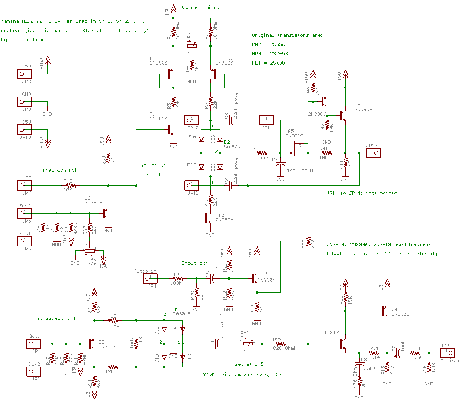
Reverse-engineered 'original' NE10400 VCF-LPF
Schematic
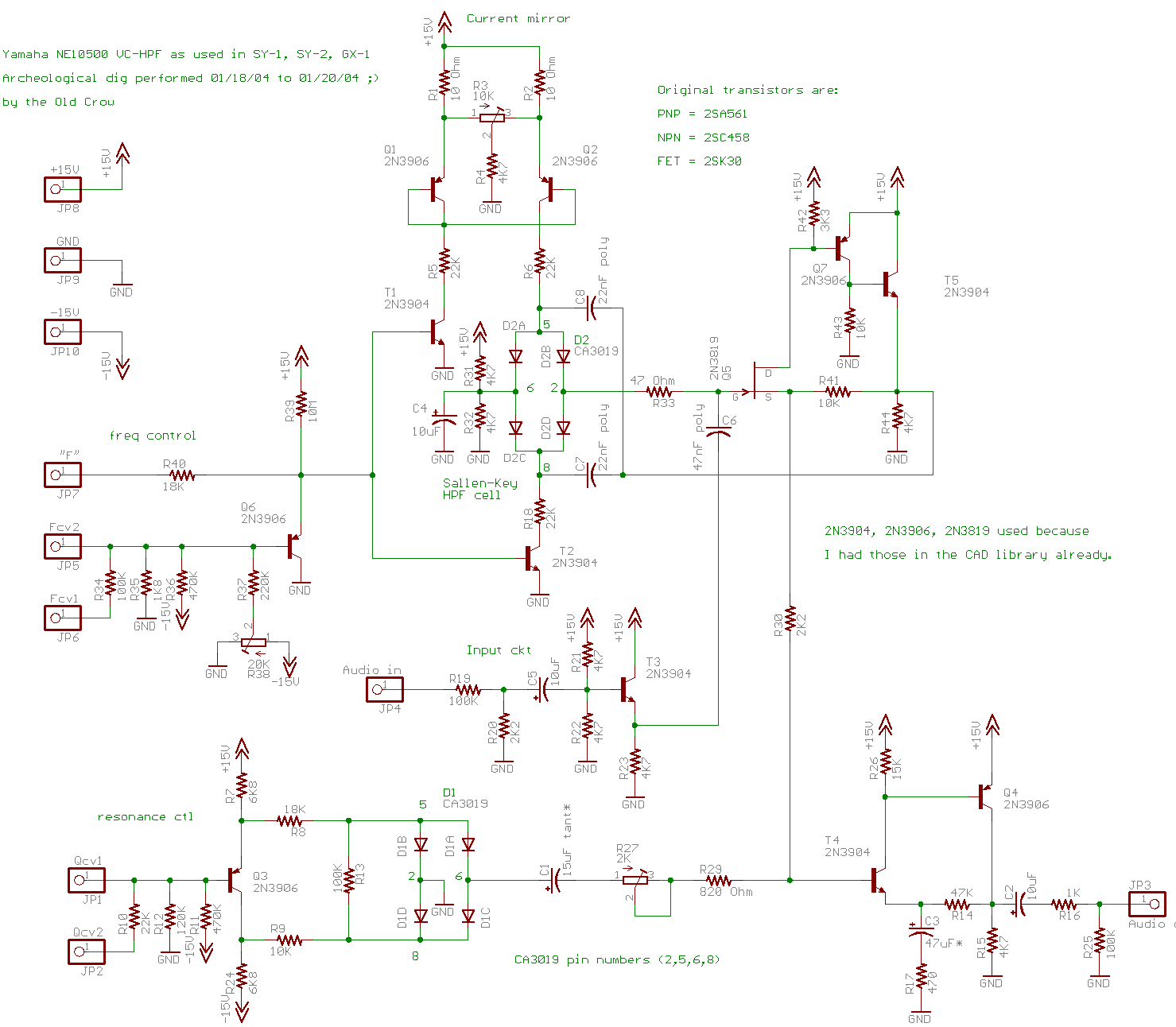
Reverse-engineered 'original' NE10500 VCF-HPF
Schematic
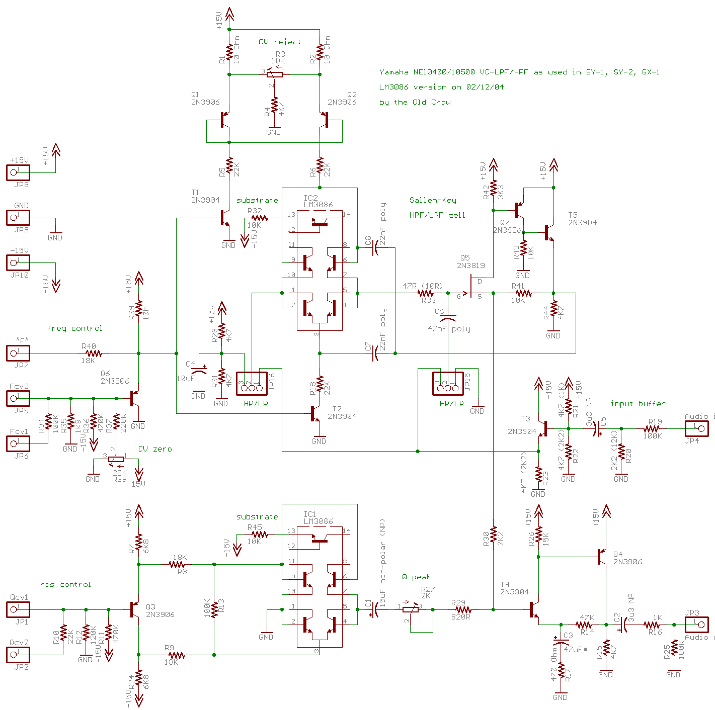
Crow's circuit using CA3086s for
matched diodes
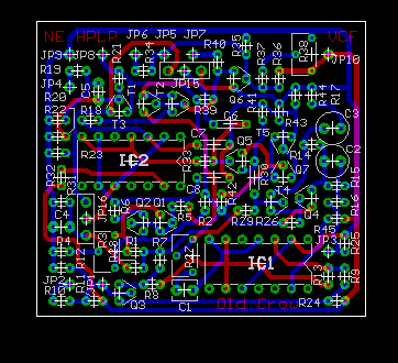
Crow's retrofit PC board artwork
Operation notes: even though the V/I converter is linear there is an exponential multipler hung on the linear input for modulation inputs. As with most Yamaha filter designs, these do not self-oscillate at high Q. In the SY-1/SY-2/GX-1, the filters are arranged LP feeding HP. Later Yamaha equipment, such as the CS-80, use a HP feeding LP arrangement. It should be noted the GX-1 also has a second HP filter as well as a BP filter in a separate signal path than these "main" filters. The extra filters are not controlled by envelope generators, but are rather used to select specific tone qualities from the VCO to be mixed in to each voice.
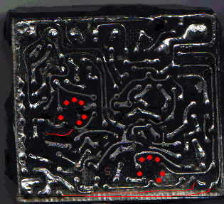
Scan of original HPF module PCB traces
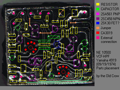
Same scan with Crow's parts
overlay