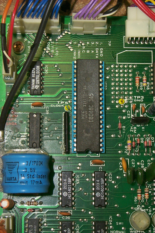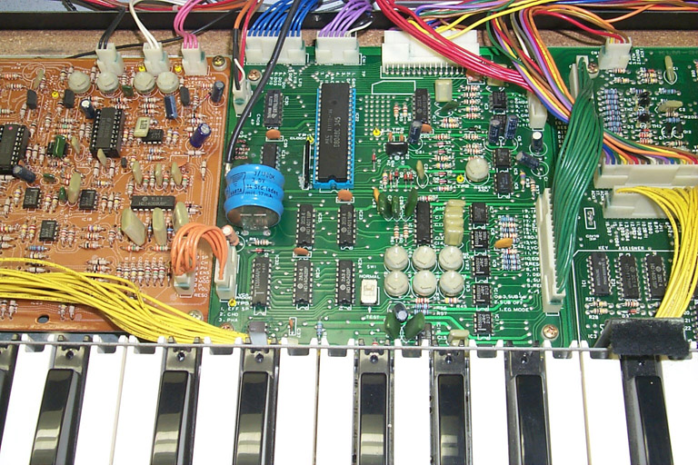
The KLM-367 is what I call the "Patch Assigner" circuit. It is in charge of keeping track of the settings of the front panel, storing the programmable presets and instructing the synthesizer how to set its voice circuits for the sound of a given patch. An Intel 8048 microcontroller directs the operation of KLM-367; it is this board that the subject of the battery repair procedure--notice the original blue Varta brand nickel-cadmium ("ni-cad") mounted on the left side of the board.
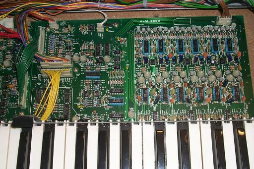
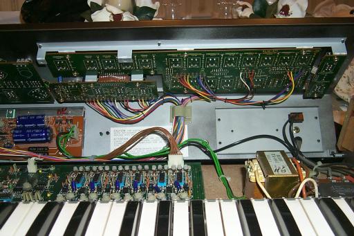
The KLM-366 is actually two circuits subsystems on one large board: the key assigner and the six synthesizer voice chains. The key assigner lives on the lower left of this board and uses its own CPU (an Intel 8049 microcontroller) to read the 61-note keyboard and select which of the six synthesizer voices is to receive the next note. The six voice chains (a chain being a VCO+subosc/MG/EG/VCF/VCA signal path for a given note) exist on the right two-thirds of the KLM-366 board.
The second set of boards are those that attach to the front panel and backplane of the Polysix. Again, from left to right:
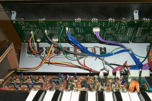
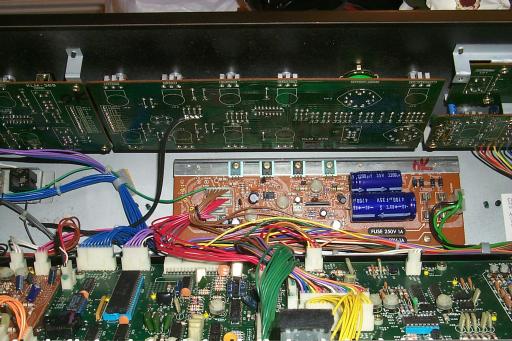
There are two boards shown in the middle illustration, the KLM-370 and the KLM-376. The KLM-370 is the board mounted similar tothe KLM-369 on the underside of the front panel. The KLM-370 holds the controls for VCF (cutoff, resonance, EG intensity and keyboard tracking), VCA (EG/gate switch and attenuator control), EG (attack, decay, sustain and release) and the effect mode and speed/intensity controls. The KLM-376 is the Polysix power supply, and can be seen mounted below the KLM-370 to the backplane of the unit. THE KLM-376 provides the various voltages needed by all these boards to operate properly.
The KLM-371 is actually three boards, a larger board and two "satellite" boards. This board set holds the controls for the arpeggiator (select, speed, mode and range), the key assign mode (hold, chord, unison and poly), the patch program and select (banks A-D, nos. 1-8, manual, write) the write enable switch and the tape enable switch.
Each of the front panel boards also holds some of the interface circuitry for their respective controls, the rest is done by the KLM-367 patch assigner board.
2-2: To, inspect the KLM-367 for battery damage, locate the portion of
your KLM-367 board that looks like this image: